
Raspberry Pi Serial Console
Serial console setup on Raspberry Pi SBCs

There are many uses for Raspberry Pi (RPi) single board computers, but one of my most common is as a small, headless Linux system. While the primary means for accessing a headless Linux system is over SSH, a serial console connection can be helpful when troubleshooting networking that SSH depends on or in early bootstrapping cases.
This post explains the hardware and software configuration necessary to set up an RPi 4 or 5 for serial console access. In many respects, this is a consolidation of the correct material sprinkled around RPi forums, etc., and streamlined for reference. Links to sources I used while sorting this out can be found in the References section at the end of this post.
Hardware and wiring
Hardware tested
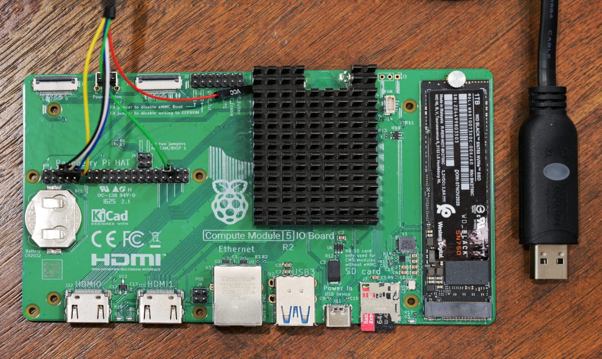
- RPi 4b and Compute Module 5 on an Compute Module IO Board; note that a standard RPi 5 is expected to perform the same.
- USB to TTL Serial Cable (a cable with hardware flow control is great; DSD TECH SH-U09G tested at 115200 baud)
- A Linux or MacOS system with Picocom installed (hereafter called a workstation)
Pi Wiring
A USB to TTL Serial Cable has DuPont-style connectors for each wire that needs to be connected to specific pins on the RPi's GPIO headers. The below pinouts are specific to each RPi model pictured. The pinouts match the overlay configurations later in this document.
Note that hardware RTS and CTS are not required, but they are supported by the Linux tty driver and provide reliable flow control.
An interactive model of the modern Raspberry Pi GPIO pinout can be found at pinout.xyz. Other resources are listed in References.
We use UART4 on the RPi4 to avoid conflict with the Bluetooth stack without disabling it. On the RPi 5, we use UART0 because it's the only GPIO-accessible UART available early enough in boot to serve as a kernel console. The uart0_console dtparam makes /dev/serial0 point to ttyAMA0 on GPIO 14/15 rather than the dedicated debug connector.
Finally, ensure that the VCC (red, hot) wire is not connected to the Pi.
RPi 5 pin assignments
| RPi 5 Pin | RPi Function | Adapter Wire | Wire Color[1] |
|---|---|---|---|
| Pin 6 | GND | GND | black |
| Pin 8 (GPIO 14) | TXD0 | RXD | white |
| Pin 10 (GPIO 15) | RXD0 | TXD | blue |
| Pin 11 (GPIO 17) | RTS0 | CTS (optional) | yellow |
| Pin 36 (GPIO 16) | CTS0 | RTS (optional) | green |
RPi 4 pin assignments
| RPi 4 Pin | RPi Function | Adapter Wire | Wire Color[1:1] |
|---|---|---|---|
| Pin 21 (GPIO 09) | RXD4 | TXD | blue |
| Pin 24 (GPIO 08) | TXD4 | RXD | white |
| Pin 19 (GPIO 10) | CTS4 | RTS (optional) | green |
| Pin 23 (GPIO 11) | RTS4 | CTS (optional) | yellow |
| Pin 25 | GND | GND | black |
Software setup
Raspberry Pi OS Lite - Trixie was used with these instructions. ubuntu-24.04.3-preinstalled-server-arm64+raspi.img works as well, but configuration may vary.
Preconditions
Flash a microSD card with an appropriate image using the Raspberry Pi Imager. Don't forget to set credentials, enable SSH, and set WiFi SSID and passphrase if that's how you intend to connect initially.
Boot up the RPi, log in over the network with SSH and make the configuration changes explained below to get a serial console set up.
RPi 5
-
Update the firmware configuration. Add to
/boot/firmware/config.txtunder[all]:dtoverlay=uart0-pi5,ctsrts dtparam=uart0_consoleIf you don't have CTS / RTS configured, remove the suffix
,ctsrtsfrom that config line. -
Configure kernel output on this terminal at boot by writing this console directive to the line in
/boot/firmware/cmdline.txt:console=ttyAMA0,115200You can leave other console directives alone if you'd like console messages to be written there too. The last console entry on this line has special treatment by the kernel: it's what
/dev/consolewill point to. This is the destination for the emergency shell and it's where systemd sends it output. -
(Optional) Ensure the RPi's OS uses the right baud rate and configures RTS / CTS signals. Override the systemd unit for the serial-getty on this UART device:
mkdir -p /etc/systemd/system/[email protected]
cat > !$/override.conf<<EOF
[Service]
ExecStart=
ExecStart=-/sbin/agetty --flow-control --noreset --noclear 115200 %I linux
StartLimitIntervalSec=0
Restart=always
RestartSec=2
EOF
This configuration relies on the
systemd-getty-generatorto create a getty on the devices configured as consoles in/boot/firmware/cmdline.txt. If you don't configure this serial connection as a console, but want to enable a getty on it, executesystemctl enable --now serial-getty@ttyAMA0. -
Shut down the RPi for now:
shutdown -h now
RPi 4
-
Become root:
sudo su - -
Update the firmware configuration. Add to
/boot/firmware/config.txtunder[all]:dtoverlay=uart4,ctsrtsIf you don't have CTS / RTS configured, remove the suffix
,ctsrtsfrom that config line. -
Configure kernel output on this terminal at boot by writing this console directive to the line in
/boot/firmware/cmdline.txt:console=ttyAMA4,115200You can leave other console directives alone if you'd like console messages to be written there too. The last console entry on this line has special treatment by the kernel: it's what
/dev/consolewill point to. This is the destination for the emergency shell and it's where systemd sends it output. -
(Optional) Ensure the RPi's OS uses the right baud rate and configures RTS / CTS signals. Override the systemd unit for the serial-getty on this UART device:
mkdir -p /etc/systemd/system/[email protected]
cat > !$/override.conf<<EOF
[Service]
ExecStart=
ExecStart=-/sbin/agetty --flow-control --noreset --noclear 115200 %I linux
StartLimitIntervalSec=0
Restart=always
RestartSec=2
EOF
This configuration relies on the
systemd-getty-generatorto create a getty on the devices configured as consoles in/boot/firmware/cmdline.txt. If you don't configure this serial connection as a console, but want to enable a getty on it, executesystemctl enable --now serial-getty@ttyAMA4. -
Shut down the RPi for now:
shutdown -h now
Workstation
If using Ubuntu Linux, install Picocom:
sudo sh -c 'apt update && apt install picocom'
In MacOS with Homebrew, install Picocom:
brew install picocom
Use
Connect your USB Serial cable to your workstation. In Linux, check for the existence of a device handle to a new TTY:
ls -la /dev/ttyUS*

crw-rw---- 1 root uucp 188,  0 Jan 25 17:11 /dev/ttyUSB0
On a mac, try:
ls -la /dev/cu.usbserial*
Boot up your RPi and start Picocom using the discovered tty:
sudo picocom --baud 115200 --flow h /dev/ttyUSB0
If you're successful, you'll see Linux kernel boot messages from the RPi. Following boot, a login prompt will be presented over the serial console. My DSD TECH cable blinks a green light when receiving data from the RPi and blinks a red light when transmitting data to the RPi.
To exit, press CTRL-a followed by CTRL-x.
Troubleshooting / Diagnostics
Checking RPi pin assignments
If using Raspberry Pi OS, you can execute the following to determine if the overlay loaded correctly. The key parts to observe in the output are that all four pins show their UART function names (e.g. TXD0 for UART0) and that CTS is set lo, which confirms the adapter's RTS is pulling the pin low.
RPi5
pinctrl get 14-17

14: a4 pn | hi // PIN8/GPIO14 = TXD0
15: a4 pu | hi // PIN10/GPIO15 = RXD0
16: a5 pu | lo // PIN36/GPIO16 = CTS0
17: a5 pn | hi // PIN11/GPIO17 = RTS0
RPi4
pinctrl get 8-11

 8: a4 pn | hi // PIN24/GPIO8 = TXD4
 9: a4 pu | hi // PIN21/GPIO9 = RXD4
10: a4 pu | lo // PIN19/GPIO10 = CTS4
11: a4 pn | hi // PIN23/GPIO11 = RTS4
Testing the serial connection
If you want to test the serial connection itself, disable use of the serial device on the RPi and disconnect from Picocom on the workstation, then run a serial test program on each system. Note that the instructions below are specific to the RPi 4 with UART4 but can easily be adapted to work on the RPI 5 with UART0 as we set it up.
Disable getty
On an RPi 4, execute:
sudo systemctl mask serial-getty@ttyAMA4
sudo systemctl stop serial-getty@ttyAMA4
Revert the change made in /boot/firmware/cmdline.txt and reboot the RPi.
Set up the testkit
On both systems using the serial connection, execute:
git clone https://github.com/codeplox-dev/serial-testkit.git /tmp/serial-test
/tmp/serial-test/pop setup
Execute test communication program
On the RPi 4, start the server:
sudo /tmp/serial-test/pop run --role server --device /dev/ttyAMA4 --flow-control rtscts
Execute the client on the workstation (assuming device /dev/ttyUSB0):
sudo /tmp/serial-test/pop run --role client --device /dev/ttyUSB0 --flow-control rtscts -n 20000
When you are finished with both, end the server session with ctrl-c.
The critical part of a test output is the report on CRC check success, e.g. Session: SUCCESS (200 sent, 200 received, 200 ok, 0 errors). If your test runs fail to peer or reliably send data at even lower baud rates, check your wiring, then conflicting use of the serial device(s). If none of these are amiss, you might need to try alternative adapters or systems.
Reliability and throughput
There can be reliability issues with a USB-to-UART converter at high baud rates and pushing data at line rate from a general purpose OS like a Linux development workstation. A useful remedy can be found in this code that sets a lower latency timer for the FTDI driver in Linux serial-testkit's device.py. Since serial console use is lower volume, this problem may not apply but it's worth noting if you adapt this UART setup for something demanding.
References
- RPi 5 GPIO Pinout
- Ethertubes RPi RTS / CTS Flow Control
- TTY Drivers; Chapter 18 of Linux Device Drivers, Third Edition
- Raspberry Pi Overlays README